Adventures in Scene Referred Space – Part Five
Recap
Welcome to our latest adventure in Scene Referred Space.
In the spirit of creating capable VFX on a budget, over the last few posts we’ve learned how to determine the dynamic range of our consumer DSLR camera so that we can generate bespoke Look Up Tables. These can then be used as Color Transforms (transforming one set of color values into another) to bring our video into a more powerful compositing workflow. If you’re diving in here, we’ve already covered a lot of ground, so be sure to catch up. Color management can be a real head-scratcher.
As a reminder, the purpose of this exercise is twofold: First it allows us to untangle our camera’s video output into something that’s useable (and reversible) in a larger color managed pipeline. That’s a process the pros can do much more easily with existing documented outputs such as Sony’s S-Log. Second, it allows us to extrapolate our video into a wider dynamic range that can be better composited alongside rendered CG elements that are not (by nature) bound to Display Referred Space (a limited color range our monitor can display). These two steps will make for more convincing, more physically accurate composites with less fuss.
First, More on Color Transforms
Even in the opening couple of paragraphs I’ve mentioned moving elements back and forth between parts of a pipeline. If you’ve ever moved an RGB file into CMYK for print in something like Photoshop you’ve already dipped your toes into Color Transforms. Things can quickly get exponentially more complex in compositing.
To oversimplify an always complex subject, in most non-professional cases, compositing is done in Display Referred Space. (Technically “Display Linear”, a zero-to-one linearization of RGB values so that certain compositing calculations designed to work in this numerical value range can operate correctly.) Some movies are also composited this way so clearly this can be a very workable approach. Working this way means much of the artistry comes down to the compositor’s eye to make sure everything “feels right” and is “bedded in the scene”. And it’s likely the way you’ve been working to date if you’ve been reading these posts.
The problem with this approach is that elements get locked into Display Referred Space early in the compositing process and once you’ve lost data it’s impossible to get it back. Later tasks such as color grading can quickly expose the challenge of losing that data and so the entire process has to be a careful balancing act.
Recent developments in graphics rendering like Physically Based Materials and HDR displays require a more robust pipeline. So the better approach is to bring every element into a common Scene Referred working space where color computation is not limited by our humble displays. And then only locking into an appropriate Display Referred Space at the very end of the pipeline immediately prior to hitting a screen.
A graphic might help here. In the ideal scenario think about your color pipeline as a series of inputs from various color spaces into a working color space, then output into a suitable color space for display on a screen.
Even with consumer camera equipment and open source CG and compositing software, here’s the pipeline we’re working toward with this series of posts:

The ideal color management pipeline we’re aiming for
Left to right we bring in a mixture of elements, some in Display Referred Space, some in Scene Referred Space, use Color Transforms (unique to each element’s color space) to align each element into a common working Scene Referred Space for compositing, then color grading, and only then “bake down” to limited color gamuts suitable for display at the end of the pipeline.
Which brings us back to our current task: creating the Color Transform shown top left in the diagram (green with a dashed line surround) for bringing video background plates shot with our digital camera into Scene Referred Space.
Generating our LUT
We finished the last post with a generated list of 4096 values based on the unique sauce of our camera, its lens, ISO, and color profile. In this post we’ll cover generating a LUT from those values and using it in combination with Open Color IO (OCIO) to create an input Color Transform to convert our footage from its 8-bit Display Referred Space origins (.mov or similar out of the camera) into a 32bit Scene Referred Space OpenEXR image sequence that’s much better for compositing.
First, the easy bit. A LUT is basically just a text file. Open up your favorite text editor, start a new plain text document and add the following header:
Version 1
From 0.000000 1.000000
Length 4096
Components 1
{
Now, it’s time to return to your spreadsheet results and copy and paste the 4096 generated exponential values from the LUT tab in immediately below the open bracket. Finally, close the bracket to seal the deal:
}
You’ll end up with something that looks like:
Version 1
From 0.000000 1.000000
Length 4096
Components 1
{
       6.00000000000E-3
       6.04825609028E-3
       6.09632144224E-3
       6.14419662233E-3
       6.19188219666E-3
       6.23937873098E-3

... many more values ...

       9.93939993959E-1
       9.93960794460E-1
       9.93980796762E-1
       9.94000000000E-1
}
Give the file a sensible name like “MyCustomLUT” or better yet something more representative of the unique characteristics it represents like “Nikon_D5200_ISO_100_NeutralGamma1”, save the text file and change the file suffix from .txt to
.spi1d
Your LUT is now ready for OCIO integration. For the curious, .spi1d stands for Sony Pictures Imageworks 1D LUT. Imageworks are the folks we have to thank for sharing OCIO with the greater filmmaking community.
Hello OCIO
As the OCIO website states, “OpenColorIO (OCIO) is a complete color management solution geared towards motion picture production with an emphasis on visual effects and computer animation. OCIO provides a straightforward and consistent user experience across all supporting applications while allowing for sophisticated back-end configuration options suitable for high-end production usage. OCIO is compatible with the Academy Color Encoding Specification (ACES) and is LUT-format agnostic, supporting many popular formats.”
Given the subject of this series of posts is VFX on a budget, we’ll be leveraging Blender’s implementation of OCIO to convert our footage. Blender can also then later be used as our compositor, or if you prefer, the industry titan, Nuke, or its open source younger brother, Natron, both of which also support OCIO, though Natron currently has some caveats when it comes to color management.
I’m going to assume a level of familiarity with Blender for this article. Like all 3D software it can be an intimidating program if you’re opening it for the first time but great power lies within. Thankfully plenty of terrific tutorials are already freely online by the likes of Blender Guru and Creative Shrimp.
Make sure you have the latest stable version of Blender installed to follow along. Even if it’s not your go-to 3D software it can still be used for your video conversion.
Locating OCIO in Blender
Each OCIO software integration comes with a human-readable configuration file. In Blender it’s found in the Blender directory a level or two down, here:
datafiles/colormanagement/config.ocio
If you’re a Windows or GNU/Linux user this’ll be easy to find. If you're a Mac user you will need to use “Show package contents” on the Blender app to peek inside to see the file structure. Also in that directory is a “luts” folder. Drag a copy of your custom .spi1D LUT into that directory. Now we need to add our LUT to the config so it can be accessed within Blender.
For safety’s sake make a copy of the existing config file and give it a temporary name like:
Config.ocio-original
If your copied file ends up being called something like “copy of…” be sure to rename it back to “Config.ocio” so Blender can located it with the filename it’s expecting. Now open it up in a text editor. You may need to give it a temporary .txt suffix so you can open it up.
Back to Our Spreadsheet
Looking back at the example spreadsheet I provided in the last post you may have noticed that there is fourth tab called “Stanza Generation” that we didn’t discuss. This will help us generate an entry for the config file that tells it what our LUT is called, how to describe it when it’s exposed in the software interface, and – critically – what dynamic range the LUT represents.
I’ve set up the sheet to automate a lot of the work for you by generating a stanza in the black box on the right.

The Stanza Generation tab will do much of the work for you.
In cells B1 and B2 go ahead and enter an easy to remember name and description for your LUT. This will be exposed within the Blender interface. The content of these cells will be automatically appended into the stanza.
In the blue and green cells immediately below, enter the upper and lower stop limits you were able to capture during your gray card shoot. This will generate the total dynamic range of your camera in cell B6 and, in turn, the math below will turn that range into a number format OCIO is expecting and append it into the stanza.
Finally add the filename you gave your custom LUT in cell B5. You can omit the .spi1d file suffix which will be automatically added.
Your stanza is now ready to add to the config file. Select the green cells F11:F24 and copy the contents. In your OCIO config file look for the section that starts with:
Colorspaces:
There you’ll see entries for the existing color spaces standard in Blender. Scroll down to the last entry before the “looks” section and paste in your stanza as the last ColorSpace entry.
One last step remains, and that is to edit the “displays” section of the config near the top of the file to reference your new entry. Nest a reference to your stanza under the appropriate display. In my case, sRGB, but depending on your monitor you may want to put it under another color space. In particular, be careful with modern Apple monitors that are now using P3, a wider gamut color space. Don’t assume sRGB – that assumption alone is a whole color management can of worms. Append a new “View” entry that references the exact name of your added stanza. Here’s what mine looks like:
displays:
 sRGB:
   - !<View> {name: Default, colorspace: sRGB}
   - !<View> {name: Filmic, colorspace: Filmic sRGB}
   - !<View> {name: RRT, colorspace: rrt_srgb}
   - !<View> {name: Film, colorspace: srgb8}
   - !<View> {name: Raw, colorspace: Raw}
   - !<View> {name: Log, colorspace: lg10}
   - !<View> {name: False Color, colorspace: False Color}
   - !<View> {name: Pauls Nikon D5200 v4, colorspace: Pauls Nikon D5200 v4}
Save the config file and remove any temporary .txt suffix if you added one. You’re now ready to open Blender. Note, if you’re a Mac user, with both the LUT and config files it’s worth double-checking any .txt suffixes haven’t hung around like a bad smell. You may need to open up “Get Info” with CMD+I to confirm or amend the actual file suffix the OS sees.
To confirm Blender has successfully read in your modified OCIO config and LUT, open Blender and head to the Scene tab in the Properties window. Under the Color Management section check the “View” drop down. If everything has been read in successfully you should see your custom Color Transform listed when the appropriate display device is active (in my case, the default sRGB). If for some reason it doesn’t appear, or if the regular entries have disappeared entirely (the config has failed to load) then double-check the stanza formatting, and make sure the config and LUT both have the correct suffixes and reload Blender:

Confirming your OCIO stanza entry has been successfully loaded.
Will it Blend?
We’ll come back to the OCIO config shortly. Onto converting our video. The first step is to convert your 8-bit DSLR video to an image sequence. PNGs are ideal. If you’re familiar with doing this in another video application go ahead and do so. Given you’re converting from an sRGB input (in my case .mov) to an sRGB output, no unnecessary Color Transforms should creep into the process. Remember we’re talking about video here that you shot using exactly the same recipe as your gray card exercise - same camera, lens, ISO, and color profile. Something you intend to use as a background plate onto which you’ll composite CG.
Here’s how to do spit out an image sequence in Blender: Set up a Node Editor window, make sure you’re in the Compositing mode of the node editor and click "Use Nodes”. Delete the “Render Layers” node that’s automatically generated. You won’t need it.
Add > Input > Movie Clip node and use it to open up your video clip. Then connect the Image output of the node to the Image input of the Composite node. While you’re at it, add an Output > Viewer node, and thread the Movie Clip node output into that as well, then check “Backdrop” in the header bar. Now as you scrub through the timeline you’ll see your video clip. By default Blender uses Right mouse button for timeline scrubbing.

A simple node network to read in a movie clip so you can export to an image sequence.
In the timeline, make sure you set the End Frame to match the length of your video. You can confirm this by scrubbing until the video stops appearing in the backdrop and then backing up one frame until it does. Then in your Properties > Render window make sure the dimensions are set to match your video. I’ll assume 1920x1080. And don’t forget to make sure it’s set to 100%.
Further down in the Properties > Render window, set a suitable output directory and make sure you choose PNG from the dropdown for image format. Give the file a name with a trailing underscore like “myimagesequence_” so that Blender can append the image sequence number in a way that makes sense.

Setting up the correct render resolution, frame range, and PNG output.
Hit the Animation Render button and Blender will render your clip to a PNG image sequence. Depending on the length of your clip this may take a few minutes.
You’re now ready to use OCIO and the LUT you built to convert that Display Referred image sequence to Scene Referred Space. Finally, the moment of truth. All your hard work has been leading up to this point.
Using our custom color transform
Open up a UV/Image Editor window and load in any frame from your PNG image sequence that adequately shows a nice range of lights and darks. With your test frame loaded drag your mouse pointer over the image with the right mouse button depressed to activate the ink-dropper and check RGB values across your frame.
Two sets of RGB values are presented. On the left are the RGB values direct from your image file. On the right (labelled CM) are the RGB values under the current color management of the window, which by default is sRGB and therefore should be identical. Given you’re examining an 8-bit Display Referred Space PNG you won’t see any number greater than 1,1,1 even in the brightest areas of the frame.
Take a moment to right-mouse drag the dropper around the image. Check dark areas, and the brightest areas. Make a mental note of the numbers.

The CM (Color Managed) RGB values max out at 1,1,1 when sampling the color chart’s white patch. A clear indication we’re in Display Referred Space.
One of Blender’s quirks is that color management isn’t just handled in the color management section of the properties window. Each image or video element has its own color space control. Now use the “N” key to open up the right-hand options drawer. Near the top of the drawer under the name and source of your PNG frame you’ll see a Color Space drop down. Change that from sRGB to your custom transform. At this point you should see a visible color shift in your image as your view transform takes hold.

The color space selection drop down is accessible on a per image basis in the “N” drawer of the UV/Image Editor window.
Now go ahead and use the ink dropper to re-sample your image. If everything has gone to plan you should find that your RGB values have shifted. The brightest areas of your image that previously topped out at 1,1,1 should now read in excess of 1. Congratulations you’re free of Display Referred Space and have arrived in Scene Referred Space.

Resampling the color chart’s white patch under our Color Transform. CM RGB values above 1,1,1 indicate we’ve moved into Scene Referred Space.
To see what’s happening under the hood, hit the “T” key to bring out the tool drawer on the left. Take a look at the RGB histogram as you flick the Color Space in the “N” drawer back and forth between sRGB and your Color Transform. You’ll notice that your transform will give the histogram of the frame a “comb” like appearance. Stop to think about this for a moment and you’ll realize this makes sense. We’ve taken a limited 8-bit color range and extrapolated it over a wider range of values. Given we’re extrapolating more so than interpolating, the peaks and valleys of the comb make sense. It’s an imperfect solution, but once we get to compositing in a future post you’ll see why this is still an improvement.

A histogram view of the PNG with the default sRGB Color Transform.

A visible “combing” appears in the histogram as our custom Color Transform extrapolates the values across a wider range.
Converting the image sequence from DRS to SRS
Our final step is to convert the PNG image sequence into a second sequence in a file format that can hold these Scene Referred Space RGB values.
Head back to the compositor node network you set up, and this time add an Input > Image node. Click open and browse to your PNG image sequence directory. Use “A” to select the entire sequence and open. The node will register that this is an image sequence and should show the correct number of frames. Delete (or bypass) the old Movie Clip node used earlier and instead, pipe through your image sequence node to the Composite and Viewer nodes. As before, you should be able to use the timeline to scrub back and forth between frames.
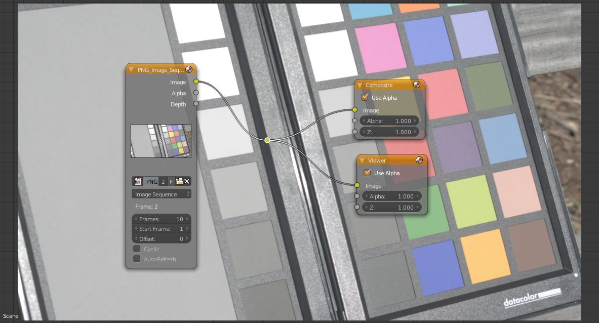
The revised node network to re-export the PNG image sequence.
Now here’s the trick. Head back to a UV/Image Editor window and select your image sequence from the dropdown, it will read as just the first frame.
As you did with the test frame, in the "N" drawer change the Color Space of your image sequence to your custom LUT. This will tell Blender that you want to read in your image sequence and apply your Color Transform.
Finally, set up your render properties to output to an OpenEXR sequence. It’s handy to output this to a separate directory and named something logical like “convertedimagesequence_”. When everything is set up, hit the Animation Render button once more. This render will bake in your Color Transform into each frame and save the resulting RGB values in floating point 32-bit EXRs that can exceed RGB 1,1,1.
Once rendering is complete, to test everything went according to plan, load in any suitable frame from the EXR sequence into the UV/Image Editor window and use the color picker to confirm the RGB values. If everything rendered correctly, your EXR frames will have preserved the new Scene Referred Values that exceed 1,1,1 in the brightest areas of the frame.

Loading an OpenEXR frame back in (note its color space is Linear) confirms our Scene Referred Space RGB values have been “baked” into the image.
A SHORTCUT OF SORTS
Above we converted the original video file to PNG, then from PNG to EXR. I walked you through this two-step process so you could clearly see the impact your transform has on RGB values. But you can actually color transform your video file directly to an EXR image sequence using a workaround. It's a little clunky but it works.
In a Node Editor/Compositor window, rather than Add > Input > Movie Clip like you did when converting to PNGs, instead Add > Input > Image and load in your video as though it were an image. The node will identify it as a Movie and allow you to set an appropriate frame range. Then, switch over to a UV/Image Editor window, select the video and apply your Color Transform in the "N" drawer just as you did before.
The limitation of this method is that if your opening frame doesn't contain anything visually significant, the UV/Image Editor can't be scrubbed back and forth through frames, so you won't be able to preview the video to test RGB values.
However, swapping back over to your compositor window and then scrubbing to a suitable frame will allow you to test that frame for RGB values in the UV/Image Editor when you select the Viewer node rather than the source video from the image browse dropdown.

You can also load in your video with an Image node rather than a movie clip node to color transform directly to an OpenEXR image sequence.
You’ve Arrived, for now
Congratulations you now have a background plate image sequence that has been color transformed by a unique LUT and OCIO config that you cooked up specific to the characteristics of your camera set up. This exercise has brought yourself a step closer to the pros and set you up nicely for compositing in Scene Referred Space.
In my next post, we’ll align our Scene Referred video background plate and Scene Referred rendered CG into a common exposure range and and start compositing in Scene Referred Space.
Thanks
If you’ve found this post hopeful, please consider following me on Twitter for updates on future posts.
Once again, a huge thanks must go to Troy Sobotka, industry veteran, and the brain behind Filmic Blender (standard in Blender as of version 2.79) who first walked through me this approach so that I may share it with you. Be sure to follow him on Twitter.
Cover image by the IIP Photo Archive used under Creative Commons licensing.